5.0 Robotics Executive CNC Routers Specifications
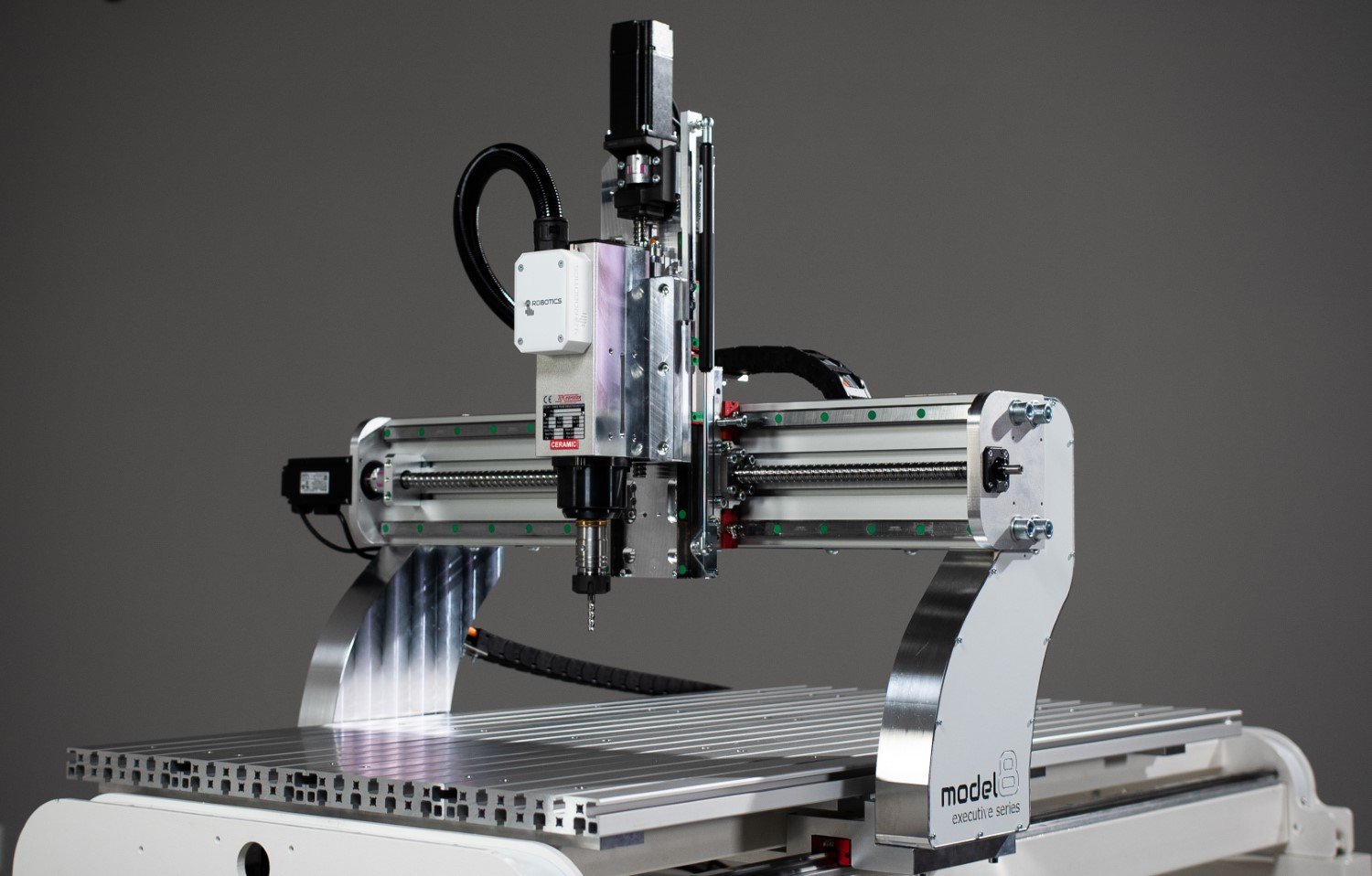
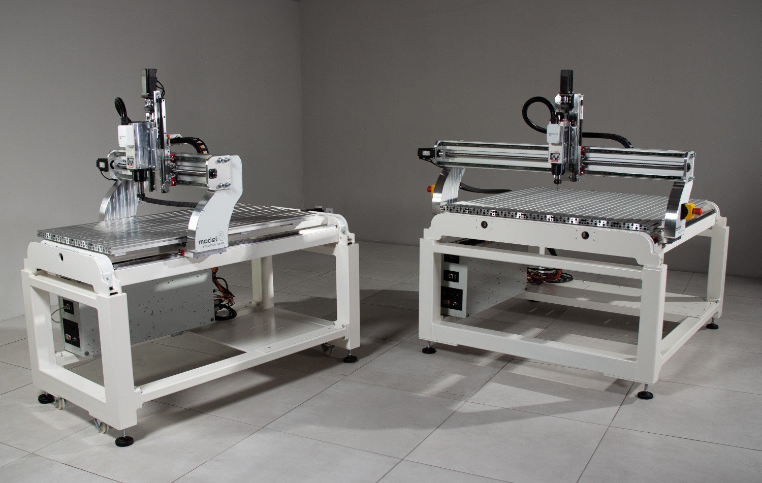
Explore the detailed specifications of the 5.0 Robotics Executive CNC Router series, designed for precision, efficiency, and versatility. This page provides an in-depth look at the features and capabilities of our machines, including X, Y, and Z travel dimensions, spindle options, and table configurations. Whether you need manual or automatic tool change systems, or advanced motor specifications, find all the technical details you need to understand how our routers can meet your specific requirements. Discover why the 5.0 Robotics series is trusted by professionals across industries for its cutting-edge performance.
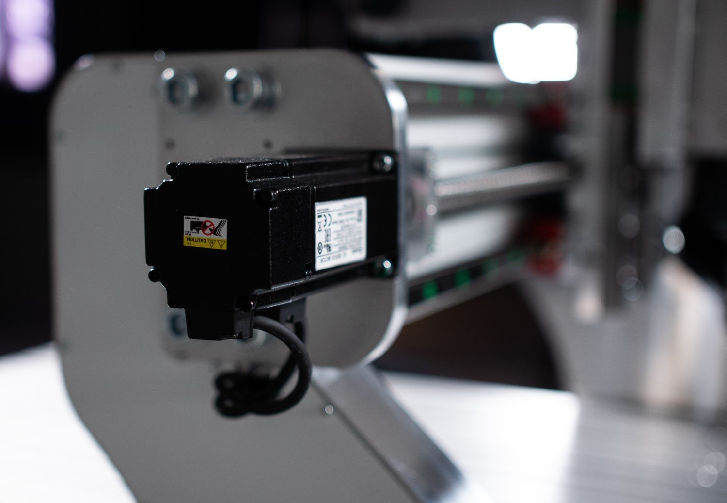
X, Y and Z travel and Closed Loop AC Servos as Standard
Model 8
Model 16
Model 32
X axis travel
610mm (24 inches) 400W AC servos.
1220mm (48 inches) 400W AC servos
1220mm (48 inches) 400W AC servos
Y axis travel
1220mm (48 inches) 400W AC servos
1220mm (48 inches) 400W AC servos
2440mm (96 inches) 400W AC servos
Z axis travel
200mm (7.87") 400W AC servos
Table work area*
The machine cutter centre to cutter travel is 620mm x 1230mm within this Table
The machine cutter centre to cutter travel is 1230mm x 1230mm within this Table
The machine cutter centre to cutter travel is 2460mm x 1230mm within this Table
* Table work area is not the same as the machine travel this is the Tslot table size on the machine.

Close Loop AC Servos on all axes - protecting your investment
-
With the closed loop system the servos are constantly watching where the machine is vs where the machine should be…. if there are any issues like a crash into a clamp, the system will stop and trigger an error. This can save a small fortune in lost work over life time of the machine.
-
Unlike steppers, or closed loop steppers, the closed loop AC servo has full torque at full RPM from 0 to 3000 RPM. Any stepper system even if three phase and closed loop, will lose torque as you raise the RPM. With closed loop AC servos there is no torque loss as RPM rises.
-
The 5.0 platform uses industry best practice with fully shielded cables. All cable shields terminate correctly at the source of the power of each device. All axes have hig quality connections on each axis allowing fast replacement of either a cable or a servo.
Spindle Systems Made in Italy
These specifications are for Model 8, Model 16 and Model 32.
2.2kW MTC Spindle
Manually change spindle system - 2.2KW ER25 collet Tekno air-cooled spindle with ER25 collet system. 24,000RPM Max cutter size 16mm shank
2.2 kW QTC Spindle
Quick change spindle system - 2.2kW Spindle with HSK32 ER20 manually changed tool holder. Tool change is carried out with a torqued Allen key wrench. The advantage is tool changes without the cost and complexity of full robotic automatic tool change. Max cutter size 13mm shank
2.2 kW QTC Spindle
2.2 kW, 30,000 RPM spindle system with fully automatic air drive pick and place ATC (automatic tool changer). NOTE: this spec requires closed-loop AC servos (which are not supplied on any machine with stepper motors) and requires a tool magazine to manage the tools for automated changing. ER20 ISO20 tooling, max cutter size 13mm shank.
RPM
All 2.2kW spindle are supported up to 24,000 RPM and the ATC spindle can realise 30,000 RPM.
Model 32 ATC
ATC on all models
Special note on model 32: Model 32 can be supplied on a 4kW ISO30 ATC system. The spindle runs ISO30 tooling with an ER32 collet system.
We now offer ATC on all machines. The ATC system is an ISO30 ATC platform that can run on single phase power.

All 5.0 Robotics Spindles are made by TEKNO MOTOR. The systme runs a 2.2kW MTC, 2.2kW QTC and a fully automated ISO30 ATC spindle. All systems run on single phase
-
Manual tool change spindles require spanners to loosen the collet nut and collet, replace cutter, and retighten. This requires an operator to change the actual tool in the spindle. These systems are incredibly reliable due to their simplcity. We can also add semi automated operation with a fixed offset sensor on the table.
-
The QTC (Quick tool change) spindle system allows an alley key mechanism (HSK32 and HSK40) system to remove and replace the tool. This allows tool holders to keep their tools loaded and their offsets saved. This is a cost effective way to apply automated tool holder and tool offset appliecation without the full ATC Automated tool change spindle system
-
The ATC automated tool change spindle has a fully hands off automated method for changing tool. The CNC controller takes over and manages collection and storage of all thet tools in a tool change magazine.
Motion System
Model 8
Model 16
Model 32
Full Ballscrew system
T7 GRADE
20mm Ballscrew on X andY Axes
16mm Ballscrew on Z Axis
Two 20mm Ballscrews on Y Axis
One 20mm Ballscrew on X Axis
One 16mm Ballscrew on Z Axis
Two 25mm Ballscrews on Y Axis
20mm ballscrew on X
16mm ballscrew on Z
50μm pitch error over 300mm and typical repeatability of 20um.
NOTE - 400W AC Servo Models will run 20mm ball screws on X and Y Axes.
Precision Linear Rails
The machines run on 20mm size profiled linear HIWIN rails with 4 carriages per axis for maximum strength and rigidity and no compromise!

All 5.0 Machines run on ballscrews and linear rails!
-
All 5.0 Robotics machines run only on ballscrews. Ballscrews are the most efficient way to drive any CNC system.
-
All linear motion systems are running on profiled linear rails. The profiled linear rails provide very high stiffness and strenght in every direction vs the direction of motion.
-
The X Y and Z axis are modular and therefore can be built separatly and calibrated and checked. Then when assembled together all axes can be tweaked and adjusted to maximise accuracy and squareness.
Technical Data
Model 8
Model 16
Model 32
Machine base
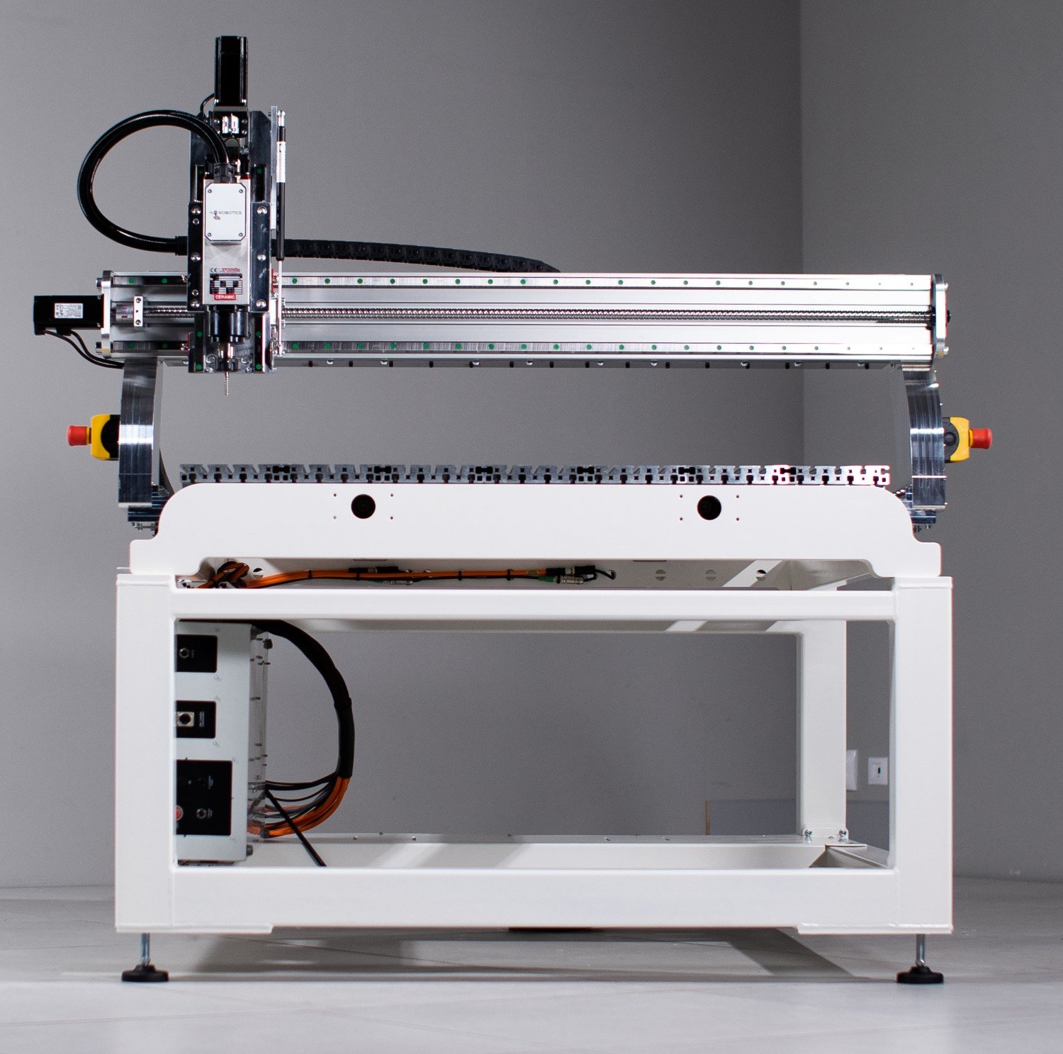
All steel frame - 10mm steel laser cut - 80 x 40 steel box section with 5mm wall thickness. Precision machined on aerospace machining center before rail and ball screw end condition assembly
Model 32 main frame is based on 80mm x 100mm steel tubes with 5mm wall. End plates 10mm laser cut steel
Floor space requirement
1350 x 2250mm with safety cover
2250 x 2250mm with safety cover
3500 x 2500mm
Weight
300 kg*
500 kg*
1000 kg*
*depends on extra’s and configuration
Power
230v 1phase - main machine will run off a 13A single phase supply. The vacuum pump supply will be separate if applied to the machine
Can be supplied single phase powered. The 4kW ATC version requires 3 phase

All Steel Frame, low footprint, mobile and single phase powered
-
All machines are bilt on a heavy duty steel frame to maximise rigidiy and performance
-
All the 50 models are small in their workshop footrint and mobile when on castors.
-
All machines can run on single phase 230V AC power! Even the ISO30 ATC can run on single phase
Machine Accuracy
These specifications are for Model 8, Model 16 and Model 32.
Machine accuracy
Straight to <0.05mm over 1000mm of stroke.
Square to < 0.05 between XY and XY plane and Z.
Repeatability <0.02mm
Rapid Feed Rate
10,000mm/min - 30,000mm/min (depends on model and drive system [stepper vs servo])
We perform a geometric accuracy test on each machine we produce
All of our measurements are made with Mitutoyo-calibrated instruments
Machine gantry
These specifications are for Model 8, Model 16 and Model 32.
Gantry bridge
160x80mm heavy-duty Alloy Bridge. For light and strong construction. High accelerations and speeds realized and high strength for maximum rigidity.
Gantry Supports
FEA designed precision machined construction - the Gantry supports are machined from solid 6082T6 Alloy on a machining centre and have been optimized for max strength transfer into the bridge from the frame.
Gantry Clearance
A standard 170mm clearance and repositionable Z height allow for an extension to 200mm clearance.
The Z axis has a 200mm stroke - so the spindle is moved fully up and out of the clearance zone.

Rigid, strong, solid and provides the stiffness needed to mill. 60mm alloy upstands and steel frame provides maximal support into the bridge
-
The connection from the Y axis (long axis) to the X axis (short bridge axes) is provided by the 60mm thick alloy upstands. These provide a very strong robust and rigid system for the bridge to leverage the drive power.
-
With up to 200mm of clearance and stroke the gantry access is much larger than most machines in this class of system. This allows very high aspect ratio parts to be milled.
-
The connection from the upstands to the ganty, the gantry to the bridge, and the bridge to the Z axis allows maximal capacity to tweak and adjust the machine to be square, while maximising strength and performance
Ready to see how the 5.0 Robotics Executive CNC Router can meet your exact specifications? Contact us today for a personalized quote tailored to your needs. Our team is here to answer your questions and guide you to the best solution for your projects. Alternatively, visit our online store to explore our full range of CNC routers and accessories. Whether you’re looking for precision, performance, or customization, we’re here to help bring your vision to life!


